Metal 3D Graphics Part 1: Basic Rendering
05 Jul 2018What is Metal, and why use it?
Metal is a powerful new GPU programming API designed by Apple. Originally it was announced in 2014 for iOS and claimed significant performance benefits over OpenGL, the standard 3D graphics API, and since 2014 it has gained the ability for general purpose GPU computation, cross-platform support between iOS and macOS, and other features. But what exactly is it, and how does it compare to OpenGL?
Both Metal and OpenGL are low-level APIs that provide programmable access to GPU hardware for 3D graphics. Both allow you to write code that will execute on the GPU to customize how 3D objects are rendered. However, OpenGL tends to hide the communication between the CPU and the GPU, whereas Metal requires you to explicitly program this communication.
This gives us two advantages: first, it allows for greater efficiency in terms of CPU and GPU communication; and second it provides an excellent learning opportunity to understand how this low-level communication works. But don't let this scare you: while this might sound horribly complicated, it's actually quite elegant and enjoyable code to write.
Finally, a quick note about what this tutorial is and what it isn't: it is meant to give a brief introduction to the very basics of rendering with Metal, with little or no prior knowledge required about Swift or 3D graphics. Later tutorials will build on this by looking at programming interesting 3D effects in Metal. However, if your goal is to get started quickly with game development, learning Metal is probably not the fastest way to make a game; instead you should look at higher-level game engines, such as Unity or others.
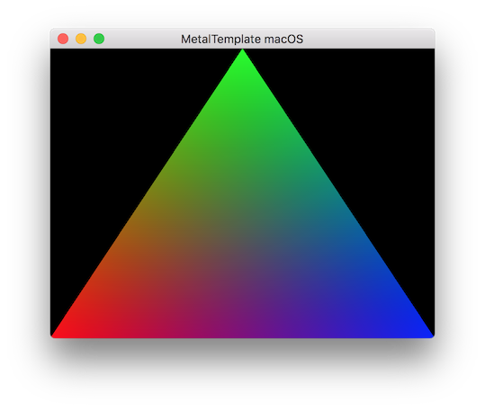
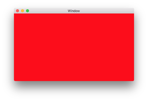
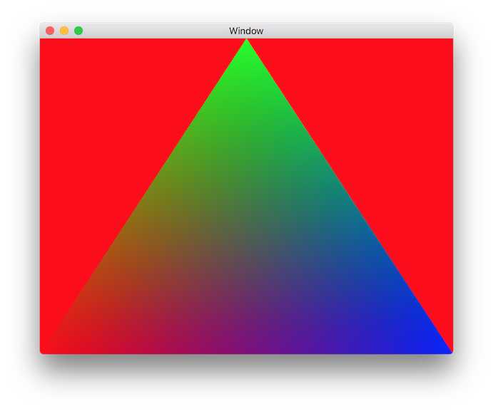
Rendering a 2D multi-colored triangle is the hello world program for graphics, and is the goal for this post. We will develop specifically for macOS since it is most convenient, but the code will actually be cross-platform with iOS and tvOS. To visualize the end goal, a screenshot of it looks like this:
Rough Sketch of Graphics Pipelines
3D graphics are generally described by geometry, which is usually specified by the vertices of triangles. These vertices are generated by code on the CPU, and then need to be sent over to the GPU for rendering. The vertex data will then be fed through a GPU pipeline, eventually resulting in a final image being rendered, which can then be displayed on screen:
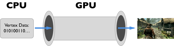
In short, a pipeline is a series of pre-configured steps that the GPU hardware takes to turn a bunch of vertex data into a final rendered image. Modern 3D graphics requires being able to program exactly what happens inside of the pipeline, and describing the pipeline via code is the central concept in Metal programming. Programming a simple pipeline that can render a single 2D triangle is the goal of this tutorial, and as we go through the code we will break this abstract pipeline into detailed individual components.
Basic Setup and Clearing the Screen
Creating a one window macOS app
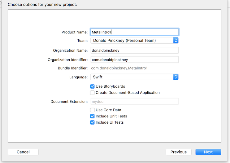
Open Xcode (make sure to install the latest version of Xcode from the Mac App Store), make a new Xcode project, choose "Cocoa App" under "macOS", and hit next. Then, fill in whatever you want for the Product Name (I'll use MetalIntro1), choose Swift for the language, make sure Use Storyboards is checked, and Create Document-Based Application is not checked. My settings look like this:
Then, hit Next, and save it somewhere. If you run the app (⌘R) then a single blank window should appear. This blank window is where we want to display our 3D graphics. Before we can write actual Metal code, we need a way for the 3D graphics to even appear in our window.
Setting Up a MetalKit View
Everything visual in macOS is represented by a view, which concretely is a subclass of NSView. We need a view in our window in which we can display the results of the Metal graphics rendering. Apple provides a prebuilt view just for this purpose, MTKView, which we will take advantage of.
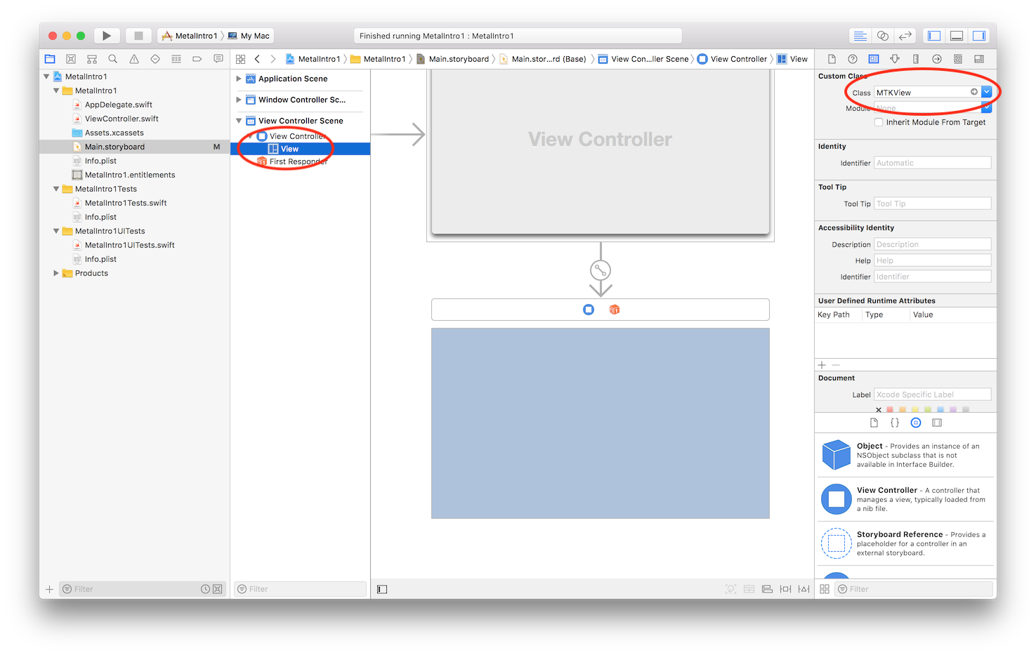
First, we need to add a MTKView to the window by modifying the Storyboard file, and then we need to configure it via code. Open Main.storyboard, select the root view of the view controller, and in the inspector panel change the class from NSView to MTKView, as shown below.
Now to configure the MTKView we need to write some initialization code in the view controller, so open ViewController.swift. We will need access to the Metal framework, and the auxiliary MetalKit framework, so add these imports at the top:
import Metal
import MetalKit
First we want to save the MTKView in a convenient variable, so add the following instance variable to the view controller class:
var mtkView: MTKView!
To initialize this variable in the viewDidLoad function add this code to the viewDidLoad function, after the super.viewDidLoad() call:
guard let mtkViewTemp = self.view as? MTKView else {
    print("View attached to ViewController is not an MTKView!")
    return
}
mtkView = mtkViewTemp
Now we can configure mtkView. The two necessary properties to configure are the device and the delegate. The device is easiest, so we will do it first. The device (of type MTLDevice) represents the actual GPU hardware. We can retrieve the default GPU and save it to the mtkView like so:
guard let defaultDevice = MTLCreateSystemDefaultDevice() else {
    print("Metal is not supported on this device")
    return
}

print("My GPU is: \(defaultDevice)")
mtkView.device = defaultDevice
If you run the app now, it should print in the Xcode console what your GPU is, but nothing will be rendered inside the window, since we haven’t told Metal to do any rendering. To set this up we need to configure the delegate property of the mtkView. The delegateis an independent object which is responsible for performing our custom rendering, whenever the mtkView asks it to. The great thing about this approach is that it is easy to write platform independent code: our view controller code is specific to macOS, but it is very short; the meat of the code will live inside the object we assign to the delegateproperty.
So we need to make a new class who’s responsibility is to render our custom graphics whenever mtkView asks it to. To do so it just needs to implement the MTKViewDelegate protocol. Let’s make a new Swift file called Renderer.swift, and add the code below to declare a new Renderer class (and import the needed frameworks):
import Metal
import MetalKit

class Renderer : NSObject, MTKViewDelegate {

    // This is the initializer for the Renderer class.
    // We will need access to the mtkView later, so we add it as a parameter here.
    init?(mtkView: MTKView) {

    }

    // mtkView will automatically call this function
    // whenever it wants new content to be rendered.
    func draw(in view: MTKView) {

    }

    // mtkView will automatically call this function
    // whenever the size of the view changes (such as resizing the window).
    func mtkView(_ view: MTKView, drawableSizeWillChange size: CGSize) {

    }
}
This class includes an initializer (with an MTKView as a parameter), and the two required functions for implementing the MTKViewDelegate protocol. We will come back to filling in the draw(in view: MTKView) function later, but first we will finish writing all of the code for ViewController.swift.
Now that we have this skeleton class, we can create an instance in the viewDidLoad function and configure mtkView with it. First, we add an instance variable for it to the ViewController class:
var renderer: Renderer!
At the end of the viewDidLoad function we create an instance of the Renderer class and configure the delegate property:
guard let tempRenderer = Renderer(mtkView: mtkView) else {
    print("Renderer failed to initialize")
    return
}
renderer = tempRenderer

mtkView.delegate = renderer
At this point we are completely done with the setup code, and now we can move on to actual Metal code. For reference, here is my final version of ViewController.swift:
import Cocoa
import Metal
import MetalKit

class ViewController: NSViewController {

    var mtkView: MTKView!
    var renderer: Renderer!

    override func viewDidLoad() {
        super.viewDidLoad()

        // First we save the MTKView to a convenient instance variable
        guard let mtkViewTemp = self.view as? MTKView else {
            print("View attached to ViewController is not an MTKView!")
            return
        }
        mtkView = mtkViewTemp

        // Then we create the default device, and configure mtkView with it
        guard let defaultDevice = MTLCreateSystemDefaultDevice() else {
            print("Metal is not supported on this device")
            return
        }

        print("My GPU is: \(defaultDevice)")
        mtkView.device = defaultDevice

        // Lastly we create an instance of our Renderer object,
        // and set it as the delegate of mtkView
        guard let tempRenderer = Renderer(mtkView: mtkView) else {
            print("Renderer failed to initialize")
            return
        }
        renderer = tempRenderer

        mtkView.delegate = renderer
    }
}
Clearing the Screen by Issuing GPU Commands
We have everything setup for us to start writing graphics code in Renderer.swift. Before we draw a triangle, we will start with clearing the screen, which will involve issuing commands to GPU, and transferring the results back to the mtkView.
Metal requires us to keep track of a queue (essentially a list) of commands that are waiting to be executed on the GPU. A Metal command queue is represented by the class MTLCommandQueue, and commands are represented by the class MTLCommandBuffer. This is an outline of what we need to do to have a full render pass working:
- At initialization time, create one
MTLCommandQueue(call itcommandQueue). - At each draw cycle, create a
MTLCommandBuffer, configure it to include the draw commands we want, and then add it tocommandQueue - Once the
MTLCommandBufferfinishes executing on the GPU, we need to display the results in themtkView.
Let's start with the first task. We need to keep track of one MTLCommandQueue for the whole Renderer class. For convenience we also want to keep track of the MTLDevice, since we will use it a lot later. So, add the following instance variables to the Renderer class:
let device: MTLDevice
let commandQueue: MTLCommandQueue
Now, inside the initializer (the init? function) add the following code to setup these variables:
device = mtkView.device!

commandQueue = device.makeCommandQueue()!
Note that we have to use the device to create a new command queue: this means that a command queue is associated with a specific device, and can only be used with that device.
We have now initialized a command queue, so now in the draw(in view: MTKView) we can create a MTLCommandBuffer, configure it, and add it to the queue. In the draw(in view: MTKView) function the first thing we do is create a new MTLCommandBuffer:
// Get an available command buffer
guard let commandBuffer = commandQueue.makeCommandBuffer() else { return }
Now, we need to configure commandBuffer to perform drawing commands that we want. First, we use a MTLRenderPassDescriptor to configure some options about input and output. When that is finalized, we then use a MTLRenderCommandEncoder to configure what drawing operations the GPU will perform.
There are a lot of options to configure for the MTLRenderPassDescriptor. Fortunately, the MTKView provides us with a pre-configured MTLRenderPassDescriptor, so we can just grab that and then change the default options:
// Get the default MTLRenderPassDescriptor from the MTKView argument
guard let renderPassDescriptor = view.currentRenderPassDescriptor else { return }

// Change default settings. For example, we change the clear color from black to red.
renderPassDescriptor.colorAttachments[0].clearColor = MTLClearColorMake(1, 0, 0, 1)
More configure options on a MTLRenderPassDescriptor will be discussed in future posts, but for now the most important option is the colorAttachments array. The first (and for now only) item in the colorAttachments array describes the output destination of the rendering. In this case, setting the clearColor property to (1, 0, 0, 1) (these are RGBA values) tells Metal to clear the color attachment to a value of (1, 0, 0, 1) before rendering. Other notable properties that the MTKView set for us include renderTargetWidth and renderTargetHeight, which were automatically set to the size of the MTKView.
This is all that we need to do to configure renderPassDescriptor. We now finalize it by converting it into a MTLRenderCommandEncoder:
// We compile renderPassDescriptor to a MTLRenderCommandEncoder.
guard let renderEncoder = commandBuffer.makeRenderCommandEncoder(descriptor: renderPassDescriptor) else { return }
At this point we would use renderEncoder to encode various drawing commands to tell the GPU to draw triangles based on vertex data. For now we just want to clear the screen, so we don't need to encode any drawing commands.
Since we are done encoding our drawing commands (none of them), we finish the encoding process:
// This finalizes the encoding of drawing commands.
renderEncoder.endEncoding()
At this point, commandBuffer as been configured via renderPassDescriptor and renderEncoder to describe a bunch of GPU commands for an entire render pass. The commandBuffer includes rendering output information, such as output width and height, the clear color, and other properties, as well as a (currently empty) list of encoded drawing commands. However, calling endEncoding() does NOT send this information to the GPU yet! This gives us control about when to actually trigger expensive drawing commands on the GPU, vs. just finish encoding them.
We are now ready to send the encoded commands to the GPU. However, it is crucial to understand that the CPU and GPU work asynchronously: so when we send the encoded commands to the GPU, it will work on completing them while the CPU code continues to run, and then finish the commands and obtain the color image result at some indeterminate point in the future. But, we need a way to know when the rendering finishes and at that time place the result into the MTKView. If we don't do this, the GPU will finish rendering, and then the result will simply disappear, since the CPU doesn't even know about the result.
Setting up the callback to place it into the MTKView is very easy, since MTKView actually provides most of the implementation for us. We just need to tell the commandBuffer to present into the MTKView's drawable:
// Tell Metal to send the rendering result to the MTKView when rendering completes
commandBuffer.present(view.currentDrawable!)
A drawable is simply a resource managed by the MTKView which Metal can write the result into.
Now, we are finally ready to send the encoded command buffer to the GPU. This is just one of line code:
// Finally, send the encoded command buffer to the GPU.
commandBuffer.commit()
Note that
commandBuffer.commit()is a bit more nuanced than just sending the command buffer to the GPU. SincecommandBufferis actually stored incommandQueue, writingcommandBuffer.commit()will prepare it for execution on the GPU, at the back of the queue. So other command buffers that are ahead of it in line (that were committed first) will execute first.
Running the code now should look like this:
And for reference the current code in Renderer.swift is:
import Foundation
import Metal
import MetalKit

class Renderer : NSObject, MTKViewDelegate {

    let device: MTLDevice
    let commandQueue: MTLCommandQueue

    // This is the initializer for the Renderer class.
    // We will need access to the mtkView later, so we add it as a parameter here.
    init?(mtkView: MTKView) {
        device = mtkView.device!

        commandQueue = device.makeCommandQueue()!
    }

    // mtkView will automatically call this function
    // whenever it wants new content to be rendered.
    func draw(in view: MTKView) {
        // Get an available command buffer
        guard let commandBuffer = commandQueue.makeCommandBuffer() else { return }

        // Get the default MTLRenderPassDescriptor from the MTKView argument
        guard let renderPassDescriptor = view.currentRenderPassDescriptor else { return }

        // Change default settings. For example, we change the clear color from black to red.
        renderPassDescriptor.colorAttachments[0].clearColor = MTLClearColorMake(1, 0, 0, 1)

        // We compile renderPassDescriptor to a MTLRenderCommandEncoder.
        guard let renderEncoder = commandBuffer.makeRenderCommandEncoder(descriptor: renderPassDescriptor) else { return }

        // TODO: Here is where we need to encode drawing commands!

        // This finalizes the encoding of drawing commands.
        renderEncoder.endEncoding()

        // Tell Metal to send the rendering result to the MTKView when rendering completes
        commandBuffer.present(view.currentDrawable!)

        // Finally, send the encoded command buffer to the GPU.
        commandBuffer.commit()
    }

    // mtkView will automatically call this function
    // whenever the size of the view changes (such as resizing the window).
    func mtkView(_ view: MTKView, drawableSizeWillChange size: CGSize) {

    }
}
Hello, Triangle!
A Review of the Metal Architecture
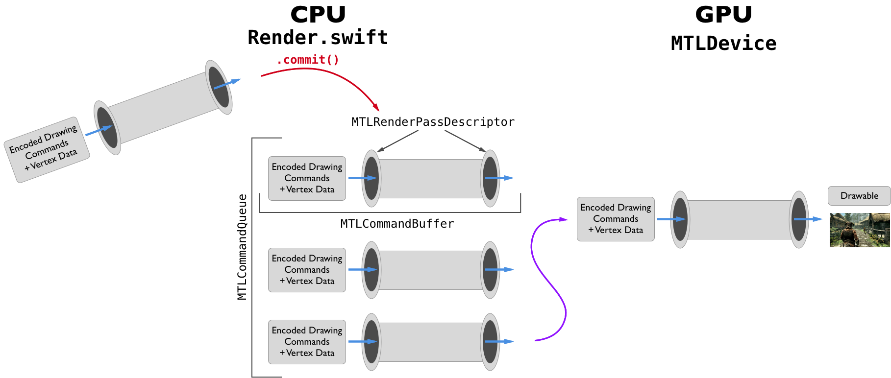
With the code to clear the screen, we have most of the infrastructure that we need for performing rendering passes. Not all, but most. Since there are a lot of different pieces to the Metal API, let's briefly organize these into a mental picture. The GPU executes pipelines which transform vertex data and encoded drawing commands into a final image result. The different Metal classes fit in as so:
- A
MTLCommandBufferrepresents the entire set of information the GPU needs to execute this pipeline: it contains the pipeline info itself, as well as vertex data and drawing commands that will be fed into the pipeline by the GPU. - A
MTLRenderPassDescriptoris used to configure the interface of the pipeline, but not the interior of the pipeline. It is like the 2 openings of the pipe. - A
MTLRenderCommandEncoderis used to prepare the vertex data and drawing commands that will be fed into the pipeline (we will see code for this in the next section). - A
MTLCommandQueuekeeps track of manyMTLCommandBuffers that are waiting in line to be executed. - A
MTLDevicerepresents the actual GPU.
Sketched as picture, the interactions of these pieces look like:
Details of the Pipeline
In the above diagram, we have written code to setup or configure pretty much all parts of it. The two pieces we have avoided so far are encoding drawing commands / vertex data, and configuring the pipeline itself. We have configured the MTLRenderPassDescriptor, which is the openings to the pipeline, how it connects to the rest, but we have not configured the internals of the pipeline.
Configuring the pipeline itself is really the whole point of graphics programming: this is the code which will render vertex data with any given effect we can code. And in Metal configuring a custom pipeline is necessary for being able to render vertices: otherwise the GPU has no way of knowing how to transform encoded drawing commands into a final image.
There are many parts to the interior of the pipeline, some of which we can write fully custom code for, and others are a fixed function provided by the GPU. Here is a diagram of the main parts of the pipeline:
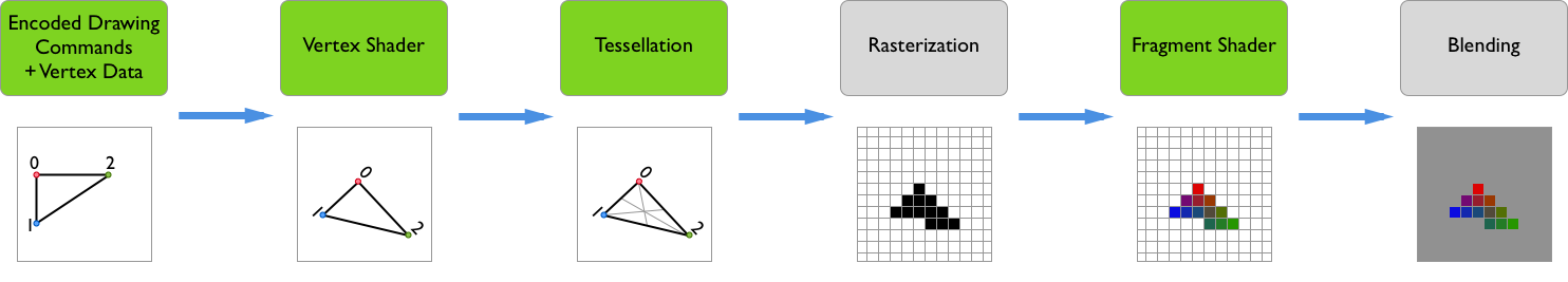
The stages marked in green are the ones that we can write fully custom code for, while the others are done mostly automatically by the GPU. Also, note that the first stage, the custom encoding of drawing commands is done on the CPU, and all other steps are done on the GPU.
- Encoding Drawing Commands / Vertex Data: The data that the GPU receives, and that must be processed in the pipeline.
- Vertex Shader: Converts the 3D vertex locations into 2D screen coordinates. It also passes vertex data down the pipeline.
- Tessellation: Subdivides triangles into further triangles to provide higher-quality results.
- Rasterization: Discretizes the 2D geometric data into 2D discrete pixels. This will also take data attached to each vertex and interpolate it over the whole shape to every rasterized pixel.
- Fragment Shader: Given the interpolated pixel data from the rasterizer, the fragment shader determines the final color of each pixel.
Tessellation is an advanced technique that will be looked at much later, but the drawing command encoding, vertex shader, and fragment shader are necessary parts for the pipeline, and we will work on setting them up now.
Creating Vertex and Fragment Shaders
Vertex and fragment shaders are written in a special programming language, the Metal Shading Language (MSL). It is based on C++, with some extra features for describing properties of vertex and fragment shaders.
We want our MSL code (running on the GPU) to share some struct definitions with our Swift code (running on the CPU), since both sides need to know how vertex data will be communicated to the GPU. We will write a C struct, which can be used by the MSL code since it is based on C++, and by the Swift code, since Swift can import C type definitions. To do so we need to setup a bridging header, so Swift knows which C header files to import.
Probably the easiest (though pretty annoying) way to setup a bridging header is to create a new Objective-C (NOT C) file in Xcode (you can call it anything), and it should prompt you to create a bridging header. Click "Create Bridging Header", and then you can immediately delete the Objective-C file you made.
We can now make a C header file which will be imported by both the MSL code and the Swift code. Create a new file, and choose "Header File". Name it ShaderDefinitions.h, and create it. Then, in the bridging header add the following:
#include "ShaderDefinitions.h"
We are now ready to define a struct which will determine what data constitutes a vertex. Since our goal is to have a 2D colored triangle, we need at a minimum to describe the position and color of each vertex. The triangle is 2D, so the positions can be described with 2 dimensions, and the colors can be described with 4 dimensions (RGBA). In vertex structs we will typically want the struct members to be vectors, in this case a vector of length 2 for the position, and a vector of length 4 for the color. To conveniently use vector types we use the simd.hlibrary. In ShaderDefinitions.h add the following include and struct definition:
#include <simd/simd.h>

struct Vertex {
    vector_float4 color;
    vector_float2 pos;
};
We have the data structure for vertex data ready, so now we can make our shaders. Create a new file, and this time choose "Metal file", and name it Shaders.metal. Now, the vertex shader is a function, which converts input vertex data into final locations of vertices on the screen. It is declared like any C / C++ function, but with a special keyword so Metal knows that it is a vertex shader. Similarly, a fragment shader is a function that converts interpolated data into a final pixel color, and also has a special keyword. Add the following to Shaders.metal:
// TODO: We need to change the parameters and return types of the shaders.

vertex void vertexShader()
{

}

fragment void fragmentShader()
{

}
We will come back to fixing the types of the functions shortly, but first we will load the shaders and setup vertex data on the CPU.
Setting up a Pipeline
To use our shaders we need to configure our own custom pipeline in Renderer.swift. To do so we configure a MTLRenderPipelineDescriptor, and then compile it to a finalized MTLRenderPipelineState, all at initialization time.
We will do this in a new function. Add this new class function stub to Renderer (we will see why we need the parameters soon):
// Create our custom rendering pipeline, which loads shaders using `device`, and outputs to the format of `metalKitView`
class func buildRenderPipelineWith(device: MTLDevice, metalKitView: MTKView) throws -> MTLRenderPipelineState {
    // ...
}
Now, inside this function we need to construct a MTLRenderPipelineDescriptor, and then configure it. We start by constructing one:
// Create a new pipeline descriptor
let pipelineDescriptor = MTLRenderPipelineDescriptor()
Now, there are only 3 properties we need to configure: the vertex shader, the fragment shader, and the format that pixel data is produced as. To load the shader code in Shaders.metal, we use the "default library": a collection of all the compiled Metal shader files in the app. We can then access the vertex and fragment shader functions by name:
// Setup the shaders in the pipeline
let library = device.makeDefaultLibrary()
pipelineDescriptor.vertexFunction = library?.makeFunction(name: "vertexShader")
pipelineDescriptor.fragmentFunction = library?.makeFunction(name: "fragmentShader")
The device is required to make the default library (and is thus a parameter for the function), since when this code is rune the Metal code must be compiled into final machine code that is specific to the device.
We also need to tell the pipeline in what format to store the pixel data. Options include how many bytes per pixel, and in what order to store red, green, blue, and alpha. But we just need the pipeline's output format to match the format of the MTKView, which is why an MTKView is a parameter. We setup this configuration with one line:
// Setup the output pixel format to match the pixel format of the metal kit view
pipelineDescriptor.colorAttachments[0].pixelFormat = metalKitView.colorPixelFormat
Lastly, we have to compile the pipeline descriptor to a final pipeline, ready to be executed on the GPU. We return the result, and in case of an error we throw the error:
// Compile the configured pipeline descriptor to a pipeline state object
return try device.makeRenderPipelineState(descriptor: pipelineDescriptor)
Now we just need to use our buildRenderPipelineWith(device: MTLDevice, metalKitView: MTKView) function to save the pipeline into an instance variable. Add this instance variable to Renderer:
let pipelineState: MTLRenderPipelineState
And in the initializer add the following:
// Create the Render Pipeline
do {
    pipelineState = try Renderer.buildRenderPipelineWith(device: device, metalKitView: mtkView)
} catch {
    print("Unable to compile render pipeline state: \(error)")
    return nil
}
Sending Vertex Data and Drawing Commands to the GPU
Now that we have a configured pipeline, we had better use it. That means we need to send vertex data to the GPU, and drawing commands telling it what to do with that data. First, let's discuss what exactly vertex data is, and then we will implement it. After that, encoding drawing commands is easy.
As described above, vertex data just stores information about each vertex. In the vertex data itself we do not specify what types of shapes (points, lines, or triangles) the vertices describe, that is done later in the draw call. The information stored in vertex data is entirely up to us: we can include any vector data in it, in any format that is convenient for us. We already decided this format above: a vector_float4 for color (RGBA), and a vector_float2 for XY screen coordinates. However, how should we scale the X coordinate? It could be a real screen coordinate, in the range of 0 to width, or it could be a normalized screen coordinate, in the range of -1 (left) to 1 (right). Likewise for the Y coordinate. Again, it is entirely up to us. As we will see, it is the job of the vertex shader to translate our arbitrary vertex data to consistent position data for the GPU to understand. For simplicity we will use normalized screen coordinates. First, we create an array of our desired vertex data in the initializer of Renderer:
// Create our vertex data
let vertices = [Vertex(color: [1, 0, 0, 1], pos: [-1, -1]),
            Vertex(color: [0, 1, 0, 1], pos: [0, 1]),
            Vertex(color: [0, 0, 1, 1], pos: [1, -1])]
If you are unsure how this vertex data relates to our final goal of drawing a triangle with red, green, and blue vertices, then I suggest getting our a piece of paper and sketching the positions of these vertices, and their colors.
This vertex data is correct, but it's not accessible by the GPU, since it is stored in CPU accessible memory, not GPU accessible memory. To make it accessible by the GPU, we must use a MTLBuffer, which provides access to CPU and GPU shared memory. Add an instance variable to Renderer for this buffer:
let vertexBuffer: MTLBuffer
And in the initializer you can now create a buffer:
// And copy it to a Metal buffer...
vertexBuffer = device.makeBuffer(bytes: vertices, length: vertices.count * MemoryLayout<Vertex>.stride, options: [])!
Note that the makeBuffer function takes length bytes stored at the given pointer in CPU memory, and copies the bytes directly into a newly allocated shared CPU / GPU buffer. In this case the buffer looks like this:
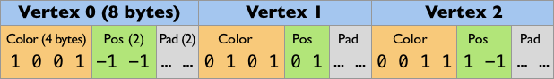
Keep in mind that the GPU doesn't automatically know anything about the structure, all it sees is the raw bytes in the bottom row of the above diagram. The only way the GPU knows about the structure of the vertex data is because we will code our vertex shader accordingly (in a bit). As a side note, the padding bytes are added into the buffer for each vertex so that 16 bytes alignment is maintained. This has ups and downs, and can be avoided, which may be discussed in a future post.
At this point we have both the pipeline and the vertex data prepared. The last code we need to write on the CPU side is to encode drawing commands for the GPU. Let's return to the function draw(in view: MTKView), and look at the section between creating renderEncoder and calling renderEncoder.endEncoding(). Between these is where we want to place our code to encode drawing commands. First, we tell it what pipeline and what vertex data buffer to use:
// Setup render commands to encode
// We tell it what render pipeline to use
renderEncoder.setRenderPipelineState(pipelineState)
// What vertex buffer data to use
renderEncoder.setVertexBuffer(vertexBuffer, offset: 0, index: 0)
We use offset: 0 since we want Metal to read the buffer starting at the beginning. Metal supports sending multiple vertex buffers in one render pass; we only have one vertex buffer so it must be at index 0, so we use index: 0.
Lastly, we need to encode the actual drawing command to the GPU:
// And what to draw
renderEncoder.drawPrimitives(type: .triangle, vertexStart: 0, vertexCount: 3)
We tell Metal to draw a triangle (other options include point, line, lineStrip and triangleStrip, possibly explored in later posts), and to start drawing using the vertex at position 0 in the buffer. Clearly we have 3 vertices to draw for our one triangle. At this point, the code in Renderer.swift is complete for this post!
Type Signatures of Vertex and Fragment Shaders
The only work we have left to do is in the vertex and fragment shaders: they are currently empty stubs! If we run the code right now, an error message like this is printed:
2018-07-03 16:12:37.685893-0700 MetalIntro1[13387:661616] Compiler failed to build request
Unable to compile render pipeline state: Error Domain=CompilerError Code=1 "RasterizationEnabled is true but the vertex shader's return type is void" UserInfo={NSLocalizedDescription=RasterizationEnabled is true but the vertex shader's return type is void}
Renderer failed to initialize
This is just saying that the type signatures of the vertex and fragment shader functions are not correct. What should they be instead?
Well, we know that the job of the vertex shader is to pre-process per-vertex data, so its input must be some form of vertex data. In fact, the vertex shader will take the entire buffer (actually a pointer to it) and a vertex ID which indexes into this buffer as input. So when we perform our draw call with a buffer of 3 vertices, the vertex shader will be invoked once for each vertex for a total of 3 times, each time with the same buffer pointer as an argument, but with vertex indices of 0, 1, 2, respectively. Omitting the return type for now, in Metal shader code these 2 vertex shader function parameters look like:
vertex ??? vertexShader(const device Vertex *vertexArray [[buffer(0)]], unsigned int vid [[vertex_id]])
Since we are using the Vertex struct here, don't forget to add #include "ShaderDefinitions.h" to the top of the Metal shader file. Now, most of this seems clear enough: we have a constant pointer to our MTLBuffer containing Vertex structs, and an unsigned integer vertex ID. But there is some new syntax here to break down.
First, device indicates in what address space of the GPU should the vertexArray be placed in. The two options are device (read-write address space) and constant (read-only address space). However, semantically and for efficiency one should use device for data which will be accessed differently by each vertex (this is our case, we have a different vertex ID for each vertex) and use constant for data which all vertices will use in the same way. Note that we don't have to specify the address space of vid since it is a simple type, not a pointer type.
Second, Metal uses the [[...]] syntax to specify Metal specific annotations. We said that we want one parameter to be the vertex buffer, which means that Metal has to call this function and pass the vertex buffer as the first argument. But Metal does not know by itself which parameter of the vertex shader function it should pass the vertex buffer to, so writing [[buffer(0)]] is how we tell Metal that this specific parameter vertexArray is where is should pass the first buffer. Note that the 0 here corresponds directly to the index: 0 in the call renderEncoder.setVertexBuffer(vertexBuffer, offset: 0, index: 0).
Similarly, Metal needs to pass the vertex ID to the vertex shader function, so writing [[vertex_id]] on the second parameter tells Metal where to pass the vertex ID.
Before we discuss the return type of the vertex shader, let's decide the return type of the fragment shader, since it is easy. Recall that the fragment shader's job is to receive interpolated data per-pixel from the rasterizer (which receives data from the vertex shader), and then output the final pixel color. At the point that Metal calls the fragment shader the GPU already knows the position of the pixel, just not the color. The only data the fragment shader needs to return is the color, and thus the return type can simply be float4. As a side note, in the Metal shader language, float4 is just the same as vector_float4 in the simd.h library.
As for the return type (call it T) of the vertex shader, the key realization is that the output of the vertex shader (T) is fed to the rasterizer, which will interpolate this output over the appropriate destination pixels, and then call the fragment shader with this interpolated data (interpolated version of T). So, the return type T of the vertex shader must match the parameter of the fragment shader, plus some Metal specific interpolation magic. As for what T is, it really can be arbitrary, except that it must provide a screen-space position coordinate. Remember, the vertex shader must convert the positions in the vertex buffer to normalized screen-space positions. For now this is easy, since our vertex buffer already contains normalized screen-space positions. But we will still need to tell Metal where this normalized screen-space position is, using a [[...]] annotation.
For rendering our triangle, our vertex shader just needs to pass the color of the vertex into the rasterizer for interpolation, and then into the fragment shader. So we declare a new struct type in Shaders.metal:
struct VertexOut {
    float4 color;
    float4 pos [[position]];
};
The float4 color is just the color data we want to pass through. There are two interesting things though about pos. First, we use [[position]] to tell the Metal rasterizer to use this field of the struct as the normalized screen-space position for performing the rasterizing / interpolation. Second, although I keep saying that we must use a normalized screen-space (2D) coordinate for the position for rasterizing, pos is actually 4 dimensional, and in fact it must be. In spirit pos is 2 dimensional, but the 3rd coordinate can be used for depth: it doesn't actually affect where the vertex is on screen, but can be used to track depth. The last coordinate is used to put pos into 4D homogeneous space: a standard, useful, and unfortunately confusing way to store locations in 3D graphics. Fortunately, both the 3rd and 4th components we do not have to worry about in this post, we just need to keep them there to make Metal happy.
We can now give final typed stubs of the vertex and fragment shader functions:
struct VertexOut {
    float4 color;
    float4 pos [[position]];
};

vertex VertexOut vertexShader(const device Vertex *vertexArray [[buffer(0)]], unsigned int vid [[vertex_id]])
{
    // TODO: Write vertex shader
}

fragment float4 fragmentShader(VertexOut interpolated [[stage_in]])
{
    // TODO: Write fragment shader
}
All the pieces of this have been explained, except for [[stage_in]]. This is another Metal attribute, which tells Metal that parameter interpolated should be fed the interpolated results of the rasterizer.
Writing Vertex and Fragment Shader Code
Finally, we get to write the actual implementations of the vertex and fragment shader, starting with the vertex shader.
The first task in the vertex shader is to fetch the vertex data of the given vertex ID:
// Get the data for the current vertex.
Vertex in = vertexArray[vid];
Now we need to create an instance of VertexOut, set its properties and return it. Starting with the color is easy:
VertexOut out;

// Pass the vertex color directly to the rasterizer
out.color = in.color;
As for the position, we need to convert our vertex data of the form \((x_v, y_v)\) to the form \((x_s, y_s, z, w)\), where \(x_s\) and \(y_s\) must be in normalized screen-space. In our case \(x_v\) and \(y_v\) are already in normalized screen-space, so we assign them directly to \(x_s\) and \(y_s\). As for \(z\) (depth) and \(w\) (homogeneous component) it suffices to use values of 0 and 1. After that we simply return out:
// Pass the already normalized screen-space coordinates to the rasterizer
out.pos = float4(in.pos.x, in.pos.y, 0, 1);

return out;
Vertex shaders which simply pass data through mostly unchanged to the rasterizer are a very common pattern, and are called pass-through vertex shaders.
Now, to code the fragment shader, all we need to do is return the final color we want. But the rasterizer has already linearly interpolated the colors of the 3 vertices among the rasterized pixels, which is exactly what we want. Thus, the only code in the fragment shader is:
return interpolated.color;
Now we can finally compile and run the code, and we see:
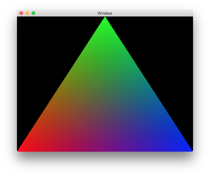
That is almost what we wanted! We just forgot that we left the clear color at red. Go back and change the clear color to black, and it should look like this:
Congratulations, you have just learned most of the fundamentals behind Metal. Perhaps this was a bit long (it was a longer post than I expected), but it is pretty cool to synthesize all of the basic concepts together.
For reference the complete sample project is available for download here.
Concluding Remarks
This post covered a lot of material; to recap, we saw how to:
- Setup a MetalKit view in a native macOS app.
- Manage a
MTLCommandQueueandMTLCommandBufferobjects to send commands to the GPU. - Configure rendering properties using
MTLRenderPassDescriptor. - Setup a pipeline with custom shaders using
MTLRenderPipelineDescriptor. - Prepare our custom vertex data, and send it over to the GPU using
MTLBuffer. - Write basic pass-through shaders.
These concepts are crucial: without them it's impossible to do any Metal programming. But the good news is that these concepts are mostly the same regardless of what you are doing with Metal: we will add complexity on top of this solid foundation.
Challenges
What's really great and fun about graphics programming is that it is easy to experiment with and try things on your own. Below are some suggestions for things to try; some are more structured than others, but they are roughly sorted in increasing order of difficulty. Do as many as you please!
- Try moving around the positions of the vertices of the triangle, making sure you are comfortable with how normalized screen-space coordinates work.
- In graphics there are usually multiple ways to achieve the same effect, but with different tradeoffs. We don't care about the tradeoffs yet, but we can experiment with different ways to do things. Make the triangle all blue by only modifying
Renderer.swift, so it looks like this: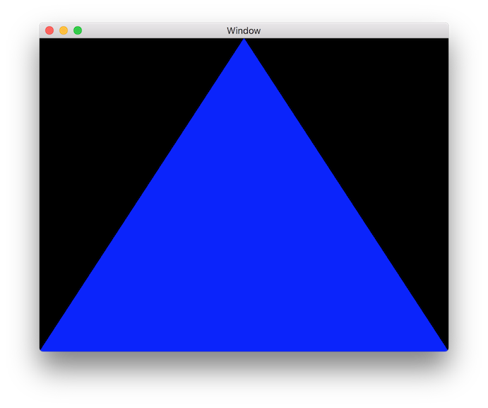 .
. - Again make the triangle all blue, but this time *by only modifying
Shaders.metal. After doing this, in what way could you simplify theVertexdata struct, buffer, andVertexOut? - Flip the triangle upside down by only modifying
Renderer.swift, so it looks like this: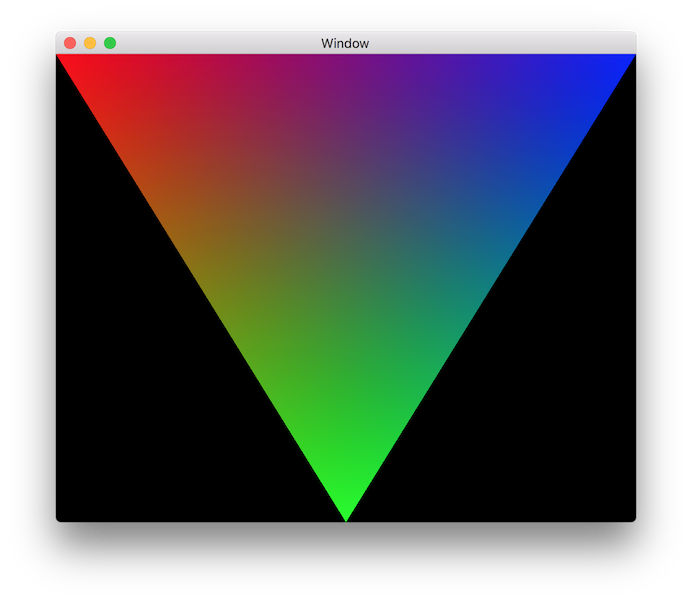 .
. - Again flip the triangle upside down but this time only modify
Shaders.metal. - Render a rectangle instead of a triangle.
- Try to render a circle by modifying
Shaders.metalonly (you can use rectangle code from 6. inRenderer.swiftif you want). Hint: you can useinterpolated.posto also determine color, BUT it is in un-normalized screen-space! It is fine if you code is hacky and does not work as the window resizes. - Try to render a circle by using the normal code (or single color code) for
Shaders.metal, but by creating a ton of triangles inRenderer.swift. - Play around and experiment with whatever you want!